Figure 1 - Rocksim Diagram
The airframe was then fitted to the motor mount
fincan assembly. This was much easier said than
done. Performance Rocketry components have an
outstanding finish, however, my components did
not fit together easily. The shoulder on the fincan
required an enormous amount of sanding to allow a
fit into the aft airframe. All of the sanding on both
the shoulder and on the inside shoulder of the airframe
was accomplished using a Black & Decker
rotary power sander. Even with power sanding tools
this material is extremely tough and required
approximately five hours of trial and error sanding
to allow the airframe to fit precisely. The fincan/airframe
junction epoxy was allowed to dry.
Next the two-inch forward bulkhead was
installed. It was epoxied to the forward center motor
mount and inner airframe simultaneously with slow
cure West epoxy. Once this dried, approximately ¼-
inch layer of West slow cure epoxy reinforced with
fiberglass filaments was poured into the airframe
forward of the bulkhead (the rocket in an upright
position). This provided another ¼-inch epoxy bulkhead
forward of the plywood bulkhead. The two 3/8-
inch U-bolts were already bolted into the bulkhead
at this point.
The Nose Cone
The aft end assembled, I began to sand the inside
part of the fiberglass airframe to fit the shoulder of
the nose cone. This is no ordinary nose cone. The
nose cone on this Honest John is five feet long with
an eleven-inch shoulder, which I cut down to eight
inches. I modified the Honest John to fly with dual
deployment; the nose cone contains a center sixinch
diameter airframe that will be used for a main
parachute bay when dual deployment recovery is
utilized. The six-inch center airframe in the nose
cone is 48 inches long and is secured in place by
foam and several plywood centering rings. A sixinch
tube coupler, 12 inches long was fitted with
bulkheads on either side with an inner 54mm airframe
to serve as the altimeter bay. The altimeters
are contained within this smaller airframe nestled
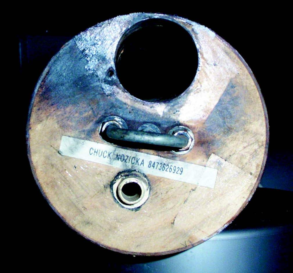
in the larger piston/altimeter bay. The entire altimeter
bay is fitted as a piston within the six-inch airframe
located in the nose cone (Figure 2). Sheer pins
secure the piston/altimeter bay. The piston/altimeter
bay is vented with ½-inch tubing to a port two feet
below the top of the rocket airframe. This allows the
altimeter bay to be unaffected by the turbulence created
by the nose cone during boost and isolates it
from the main airframe (drogue compartment) pressurization
during drogue deployment. The altimeter
bay must be isolated from the drogue ‘chute compartment
because deployment of the drogue could
interfere with the altimeter function. A resetting of
the altimeter or premature main deployment could
result. (Refer to Figure 1)

Figure 2